VIDEOS
The harmonious working movement, the core of functioning machines
The designer defines the boundary conditions for his work movement in his motion plan. Areas with constant speeds, synchronous operation with other movements, points to be approached and much more are defined in it.
We calculate the motion diagram from the motion plan. In doing so, we fulfill the boundary conditions of the workflow through harmonious movement.
This calculation must be carried out with great care, as the function, noise and vibrations of the machine are decisively influenced positively by this harmonious movement.
The care taken in designing this movement determines the success of your machine
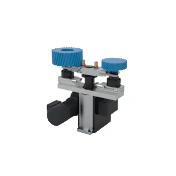
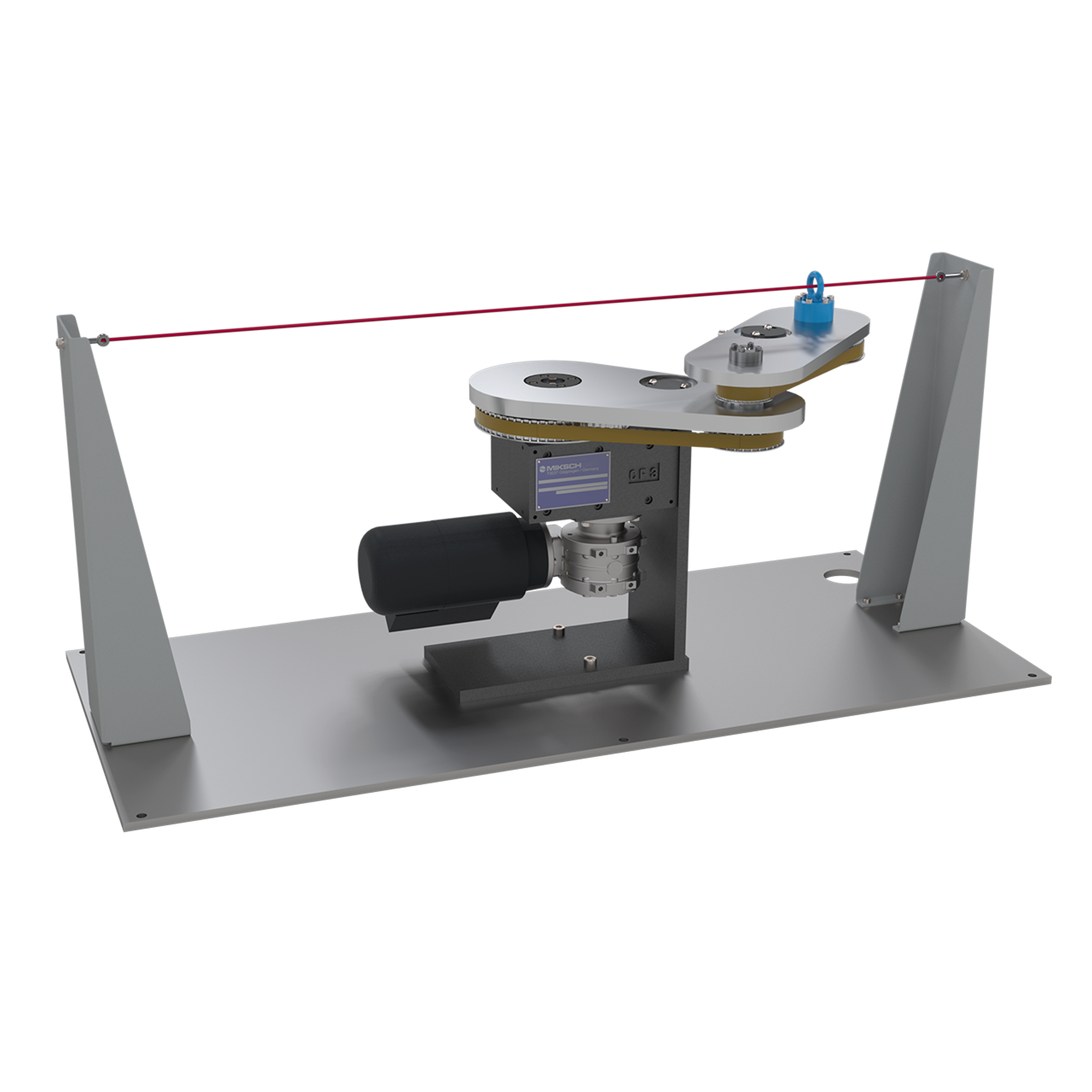
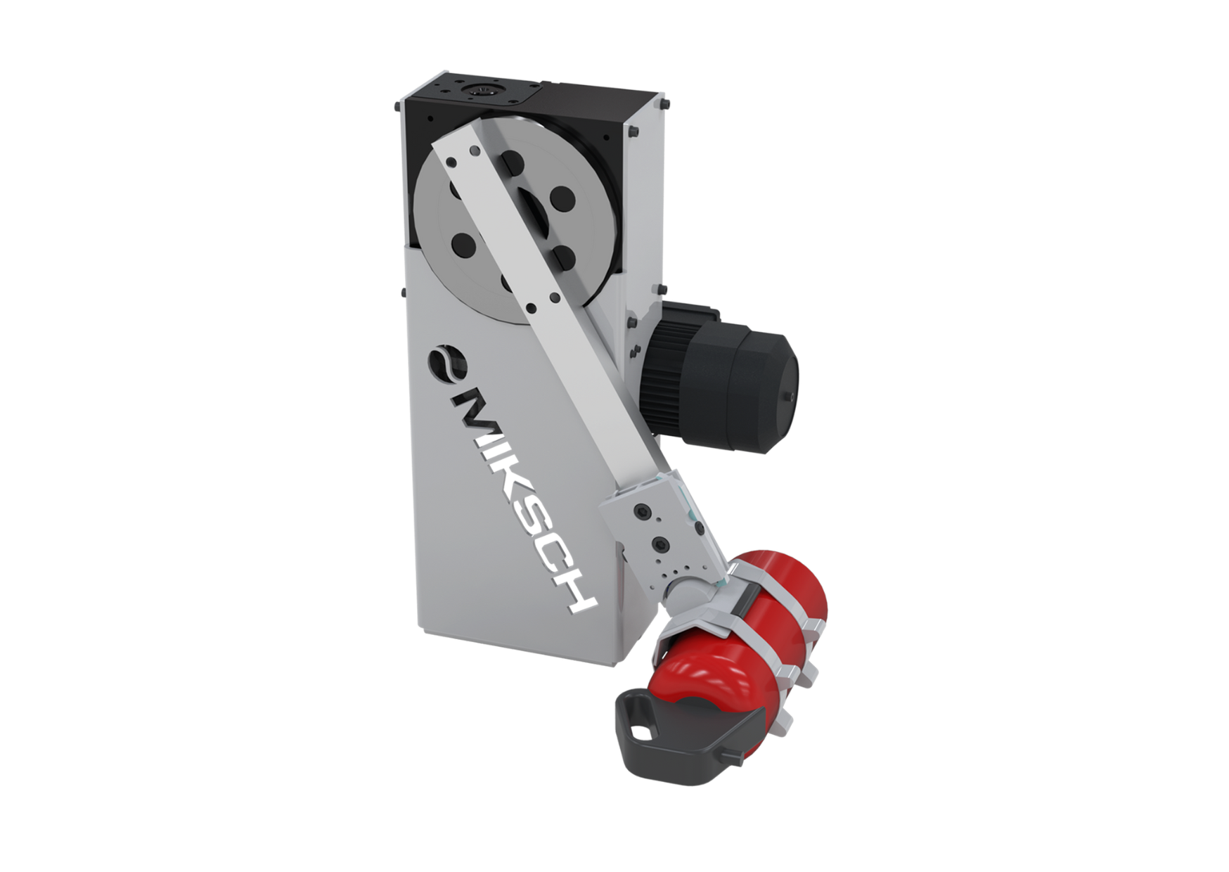
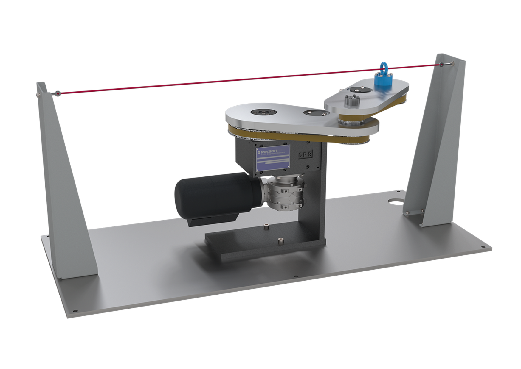
Cam gears in conjunction with articulated gears allow a large number of motion tasks to be carried out. The harmonious motion is specified at the output of the articulated gear. The back calculation of the motion through the articulated gear takes into account the motion distortion in the curve profile. By skillfully adjusting the articulated links with servomotors, the motion can be specifically modified over large areas.
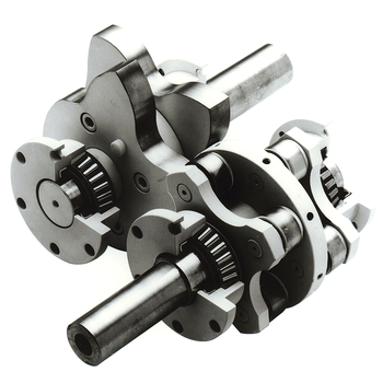
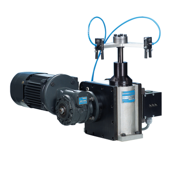
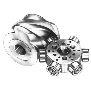
This harmonious movement is realized by many different types of cam gears
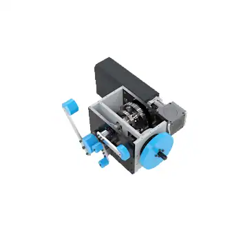
There are suitable arrangements of cam gears for many applications. Linear or rotating drive of the cams, linear, pendulum or step movements of the output element are possible. The cams and output elements are arranged in a plane or in space with parallel or crossed axes of rotation. Common examples are shown, special forms are checked for their feasibility on request.
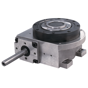
Reliably reproducible drive movement with high power density through the cam gear in combination with fast and low-power electronic control on the articulated gear leads to your success.